Layout Planning Reliable train operation starts with a solid track plan. Many plans you see look great on paper but when laid out full size in the defined space fall short of acceptable standards. You may have discovered this while researching plans for your layout. Seldom does a plan fit your exact space, accomplish the track operations you want or meet your expectations for scenery and structural elements. If you have a design in mind, or sketched out, you may have experienced difficulty getting all the pieces to fit. Model Scenery and Structure has a solution!
Model Scenery and Structure uses our Design Inquiry Form and active ongoing interaction with you to develop track and design plans that meet your layout objectives. These plans reflect your railway operating preferences with integrated space allocation for structural elements.
including roadways, buildings, bridges, water features, landscaping and terrain topography. All track and design plans will comply with NMRA standards for turn radius (with easements and super elevation), centerline spacing, grades (with transitions), turnout sizes and any other applicable standards. Model Scenery and Structure can also rework, or cleanup, a plan or sketch you may already have and bring it up to standards. Strict adherence to NMRA standards assures solid layout design and most importantly reliable train operation.
The Bench Plan, Final Design Plan, and Wiring Plan along with the Switchboard Diagram for Computer Control may be incorporated in the Layout Plan Set.
Refer to the Design section for more information on our various Plan Sets.
Layout Plan Set The Layout Plan Set is made up of the plans you choose to have prepared. The Bench Plans, Final Design Plan, Wiring Plans and the Switchboard Diagram for Computer Control may be incorporated in the Layout Plan Set. Each of these plan sets are discussed below and in the Design section. Your Layout Plan Set is a comprehensive, detailed set of CadRail drawings that will make building your railway a manageable and enjoyable experience. With the guidance provided by the plans you will eliminate redoing, rebuilding, overbuying and a lot of frustration. The Material List that is included with all but the Basic Track Plan is a valuable tool when ordering materials. Get it right the first time! We are sure you will find the amount invested in the plans is more than paid back by the time the project is completed. The finished product is a model railway that operates reliably providing years of trouble free service and looks exactly like the layout you designed.
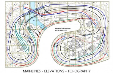
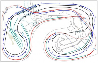
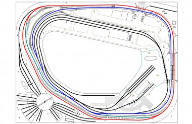
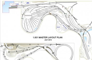
Basic Track Plan The Basic Track Plan is an drawing of your layout project with accurate track and turnout geometry! Drawn in CadRail, with track, turnouts and track elevations indicated all according to NMRA Standards. Utilizing the information on your completed Design Inquiry Form the track will be designed to accommodate your locomotives and rolling stock reliably with ample curve radius’, turnout size and track centerline spacing. Easements for all curves and transitions for each elevation change are designed in the plan. Space for elements such as structures, hills, mountains, water features, roadways etc. will be blocked out on the plan. We will complete a first draft for your review and then work with you to refine the plan. Several reworks are expected in the Basic Track Plan development and included in the fee. The reworks allow you to tweak the plan so it’s just right!
The Basic Track Plan is useful as a platform from which further development of the layout design and operation can be derived. It’s a prerequisite for the Final Design Plan and Layout Plan Set development. The Basic Track Plan can be used to build your layout if you can handle the bench work, deck details and the wiring without guidance. The Basic Track Plan provides adequate information to produce a functional and reliable layout.
Basic Track Plan fees are ZERO COST when you go to the next step in layout planning. The initial fee, starting around $100ºº, depending on the size of your proposed layout, is applied toward the cost of the Layout Plan Set if you choose to proceed with the project. The Basic Track Plan fee is determined after we have had a chance to review the completed Design Inquiry Form and discuss he project with you directly.
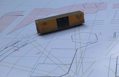
Full Size Plan Prints are available from Model Scenery and Structure. These prints are modified to show track, turnouts, switch machines and key elements like roadways, signals, buildings, water features etc. in detail. The Full Size prints are taped or glued to the layout deck to create your layouts exact track geometry and features in full scale. This eliminates drawing the plan on the deck mechanically and creates an accurate representation of the layout. The prints are 11″ x 17″ and have grid lines that make alignment a snap. This is a huge timesaver and assures the completed project will look like the plan.
Final Design Plan Set
The Final Design Plan Set is a complete CadRail drawing set. The Final Design Plans will use the Basic Track Plan as a starting point. All track, turnouts and track elements will be located on the Final Design Plan and specified in detail. Roadways, water features, structures, bridges, tunnel portals etc. will also be located and detailed. Track and topography elevations will be called out. A material list will be prepared for all track work, turnouts and structural elements. The Final Design Plan is generally a set of five to nine pages or more. Refer to the Design section for more information on the Final Design Plans and our fee structure.
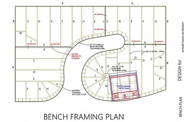
Bench Plan The Bench Plan is based on an open frame design that supports the layout deck. This allows access to hidden track from below the layout and facilitates component wiring not to mention retrieval of derailed locomotives and rolling stock. Troubleshooting, maintenance and adding components is easy with unrestricted access below the table. On elevated, multi-level layouts and those using a helix the bulkhead framework supports the various elevations and shapes of the deck. The track bed and terrain topography supports are integral portion of the bench work. The completed bench and deck are ready to receive track and wire mesh for the plaster that shapes the terrain, hills
and mountains. Foam can be used in lieu of wire and plaster. The open frame bulkhead fabrication can be compared to building a boat upside down. The Bench Plan provides detailed CAD drawings of all bulkheads, deck cuts and elevations. Support legs or cabinetry with a power component module or control panel are included in the plan. All cutting dimensions and a complete material list are provided to simplify bench fabrication. The bench can be designed for modular fabrication should you plan to relocate or add to the layout in the future. The Bench Plan Set may be incorporated in the Layout Plan Set. The fee structure for our Plans can be found in the Design section.
Wiring Plan
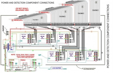
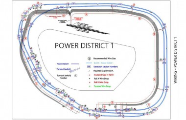
The Wiring Plan is a detailed diagram, or schematic, detailing track, turnout and component wiring for a DCC or DC operating system. Pin to pin connections are called out along with wire gauges and wire runs. Model Scenery and Structure has extensively used and prefers Digitrax™ DCC products. They provide most every function needed on the layout. (Other brands can also be used.) Wiring schematics for power, power management, turnout control, detection, signaling and sound control specified in the Basic Track Plan or Final Design Plans are provided in the DCC Wiring Plan. DC system schematics for track power, block power control, turnout control and auxiliary modules for signals, sound and train control via sensors called for in the Basic Track Plan or Final Design Plans are included in the DC Wiring Plan. The design, configuration and wiring schematic for the DCC component boards or the DC control panel are included in the wiring plan. The Wiring Plan provides a guide for reliable wiring of your layout. This assures the track and components will function as expected. This plan saves time and allows for efficient use of wire in the correct gauge run to the correct connection points. The Wiring Plan Set may be incorporated in the Layout Plan Set. The fee structure for our Plans can be found in the Design section.
Switchboard Diagram
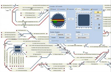
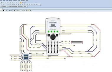
Computer Control for hands free automatic operation can be integrated in your DCC layout plans! Model Scenery and Structure will develop and configure your Switchboard Diagram for computer train control. We recommend and use the RR&Co.™ TrainController™ software connected to a PC running Windows® 7 or 8 through the RR-CirKits™ Loco-Buffer™ interface. Used in conjunction with the Digitrax™ DCC components your layout can operate manually, automatically or both simultaneously. The Switchboard Diagram, or plan, of your layout is the basis for all computer operations. The Switchboard components are configured to define each block, detection section, transponder zone, turnout, turntable, signal, sound module and all other digital components included in your layout. Each of your locomotives data is recorded and train schedules are input to the program. When completely configured the system can be controlled manually with a Digitrax™ handheld throttle, the RR&Co.™ SmartHand™ throttle, with SmartHand Mobile™ or on your Android™ or iPhone™ (from anywhere) and the entire layout can run automatically controlled by your computer or SmartHand Mobile™ device.
This is state-of-the-art model railroading!
Model Scenery and Structure can prepare the Switchboard Diagram and configure the components in the software program to get your trains rolling . . . . Automatically!
The Switchboard Diagram for Computer Control may be incorporated in the Layout Plan Set. The fee structure for our Plans can be found in the Design section.

